Machine Instructions in Computer Organization Study Notes with Examples
Machine Instructions
Computer Instruction
A binary code used for specifying micro operations for computer. Instruction Code Group of bits used to instruct the CPU to perform an specific operation.
Instruction Set: Collection of instructions.
Instruction Representation: Each instruction has a unique bit pattern, but for human beings a corresponding symbolic representation has been defined. e.g., ADD, SUB, LOAD, etc.

Instruction Cycles
Instruction cycle consists of following phases
- Fetching an instruction from memory.
- Encoding the instruction.
- Reading the effective address from memory in case of the instruction having an indirect address.
- Execution of the instruction.
Instruction Format
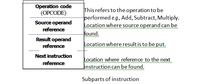
An instruction consists of bits and these bits are grouped up to make fields. Some fields in instruction format are as follows
- Opcode which tells about the operation to be performed.
- Address field designating a memory address or a processor
- Mode field specifying the way the operand or effective address is
Different types of Instruction formats
some common types are as given below
- Three address instruction format
- Two address instruction format
- One address instruction format
- Zero address instruction format
Three Address Instruction Format
- This system contains three address fields (address of operand 1, address of operand 2 and address where result needs to be put).
- The address of next instruction is held in a CPU register called Program Counter (PC).

Here, the number of bytes required to encode an instruction is 10 bytes i.e., each address requires 24 bit = 3 bytes. Since, there are three addresses and one opcode field so,
3 x 3 +1=10 bytes.
The number of memory access required is 7 words, i.e., 4 words for instruction fetch, 2 words for operand fetch and 1 word for result to be placed back in memory.
Two Address Instruction Format
- In this format, two addresses and an operation field is there.
- The result is stored in either of the operand address e., either in address of first operand or in the address of second operand.
- CPU register called Program Counter (PC) contains the address of next

One Address Instruction Format
- One address field and an operation field.
- This address is of the first operand.
- The second operand and the result are stored in a CPU register called Accumulator Register (AR). Since, a machine has only one accumulator, it needs not be explicitly mentioned in the instruction.
- A CPU register (i.e., Program Counter (PC) holds the address of next
- In this scenario, two extra instructions are required to load and store the accumulator contents.

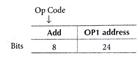
- Number of bits required to encode an instruction is 4 bytes. i.e., each address requires 24 bits = 3 bytes. Since, there are one address and one operation code field, 1* 3 + 1= 4 bytes.
- The number of memory access required is 3 words i.e., 2 words for instruction fetch +1 word for code for operand fetch.
Key Points
- Total number of bytes to encode an instruction = number of address fields * Bytes required to store an address + bytes required to store operation code. 2 * 3 + 1 = 7 bytes.
- The number of memory access required is 6 words e., 3 words for instruction fetch +2 words for operand fetch +1 word for result to be placed back in memory.
Zero Address Instruction Format
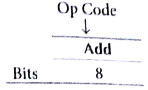
- Here, an stack is included in the CPU for performing arithmetic and logic instructions with no addresses.
- The operands are pushed onto the stack from memory and ALU operations are implicitly performed on the top elements of the stack.
- The address of the next instruction is hold in a CPU register called program

e.g, Add
Top of stack <— Top of stack I- second top of stack.
Sorting in Design and Analysis of Algorithm Study Notes with Example
Follow Us On Cyber Point Solution Youtube Channel : Click Here
Follow Us on Social Platforms to get Updated : twiter, facebook, Google Plus
Learn More Ethical Hacking and Cyber Security click on this link. cyber security
