
TCP or IP Protocol Suite Tutorial Study Notes for Beginners with Examples
TCP/IP Protocol Suite
The TCP/IP protocol suite used in the Internet, was developed prior to the OSI model. Therefore , the layers in the TCP/IP protocol suite do not exactly match those in the OSI model. The original TCP/IP protocol suite was defined as having four layer.

As we can see in the above diagram TCP/IP (Transmission Control Protocol /Internet-working Protocol) model contains four layers. The first three layers of TCP/IP model (Network Interface layer, Internet layer and Transport layer) provide physical standards, network interface, Internet working and transport functions that corresponds to first four layers of the OSI model.
The three top most layer in the OSI model, however are represented in TCP/IP by a single layer called the Application layer.
Transport layer: is designed to allow peer entities on the source and destination, host to carry on a conversation.
Internet layer: permits the host to inject packets into any network and let them travel independently to the destination.
The data link layer:is the networking scope of the local network connection to which host is attached.
Error Control (Detection and Correction)
Many factors including line noise can alter or wipe out one or more bits of given data unit,

Key Points ……………
Reliable systems must have mechanism for detecting and correcting such errors.
- Error detection and correction are implemented either at the data link layer or the transport layer of the OSI model.
Error Detection
Error detection uses the concept of redundancy, which means adding extra bits for detecting errors at the destination.
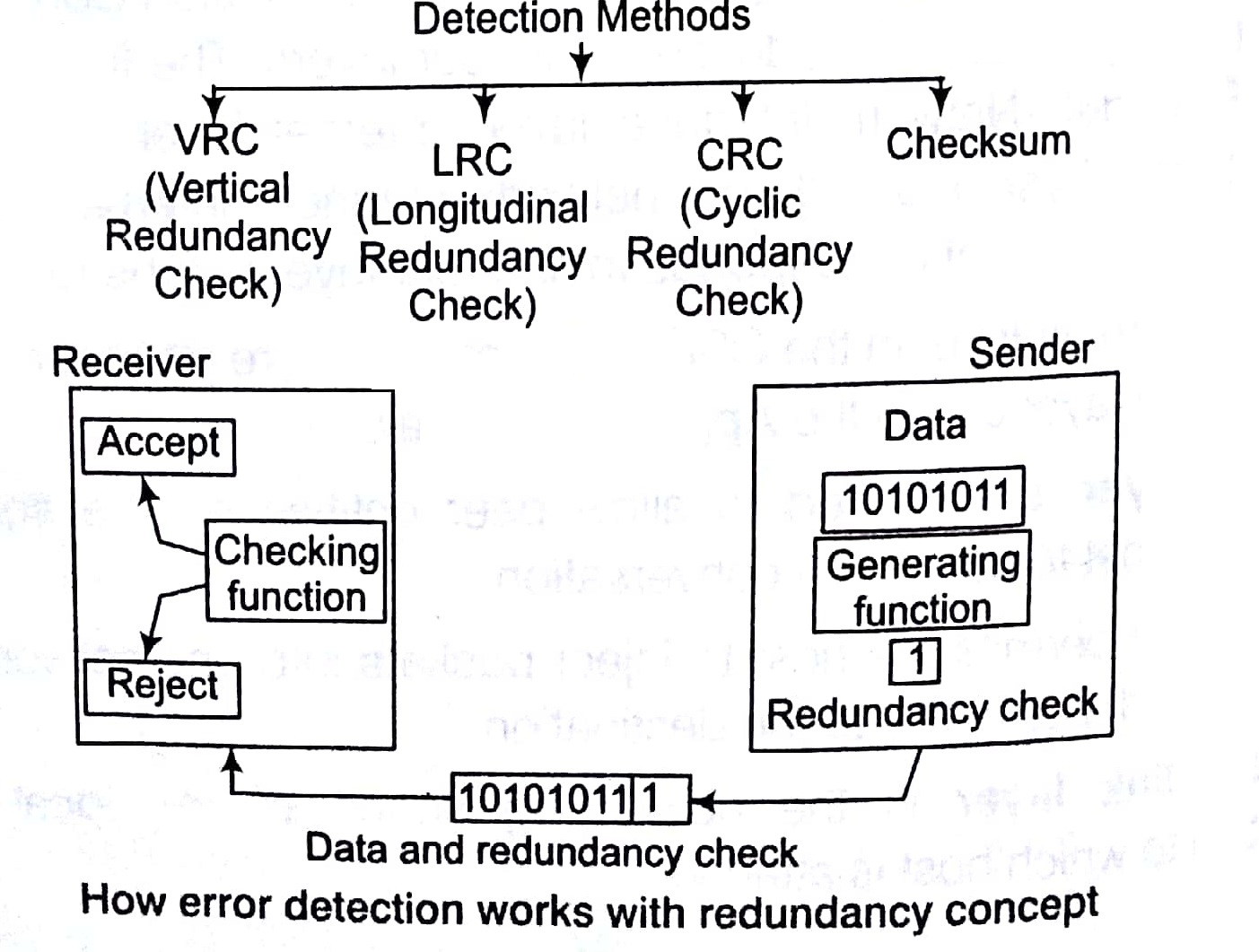
Note Checking: function performs the action that the received bit stream passes the checking criteria, the data portion of the data unit is accepted else rejected.
Vertical Redundancy Check (VRC)
In this technique, a redundant bit, called parity bit, is appended to every data unit, so that the total number of 1’s in the unit (including the parity bit) becomes even. If number of l’s are already even in data, then parity bit will be 0.

Some systems may use odd parity checking, where the number of 1 ‘s should be odd. The principle is– the same, the calculation is different.
Longitudinal Redundancy Check (LRC)
In this technique, a block of bits is divided into rows and a redundant row of bits is added to the whole block Original data at sender end
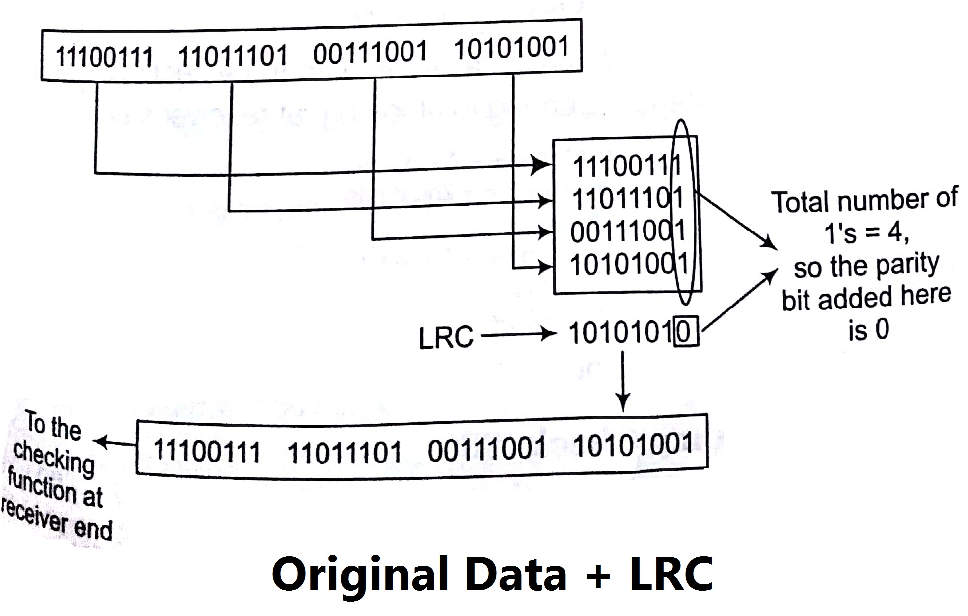
Note: The first parity bit in the 5th row is calculated based on all first b second parity bit is calculated based on all second bits and so on.
Checksum
There are two algorithms involved in this process, checksum general at sender end and checksum checker at receiver end.
The sender follows these steps
- The data unit is divided into k sections each of n
- All sections are added together using 1 ‘s complement to get the sum
- The sum is complemented and becomes the checksum.
- The checksum is sent with the data.
The receiver follows these steps
- The received unit is divided into k sections each of n
- All sections are added together using 1’s complement to get the sum,
- The sum is complemented.
- If the result is zero, the data are accepted, otherwise they are rejected.

- At receiver end, we break this data stream into three sections each 06 bits and perform steps according to algorithm at receiver’s end.
10101001-4 ←1st 8 bits
00111001 ← 2nd 8 bits 11100010
00011101 ←3rd 8 bits
11111111 Sum
00000000 ←Complement
- All bits 0 (zero) indicates number error in data.
Cyclic Redundancy Check (CRC)
CRC is based on binary division. A sequence of redundant bits called to or the CRC remainder is appended to the end of a data unit, so need resulting data unit becomes exactly divisible by a second, Predetermined binary number. At its destination, the incoming data unit is divided Same number. If at this step there is no remainder, the data unit is assumed to be intact and therefore is accepted.
e.g., Generate CRC code for a frame 100100, using the generator.
G (x) x3 + x2 + 1
G (x) = X3 + X2 + OX1 + X0
We do not have xl term that’s why we put a 0 for that.
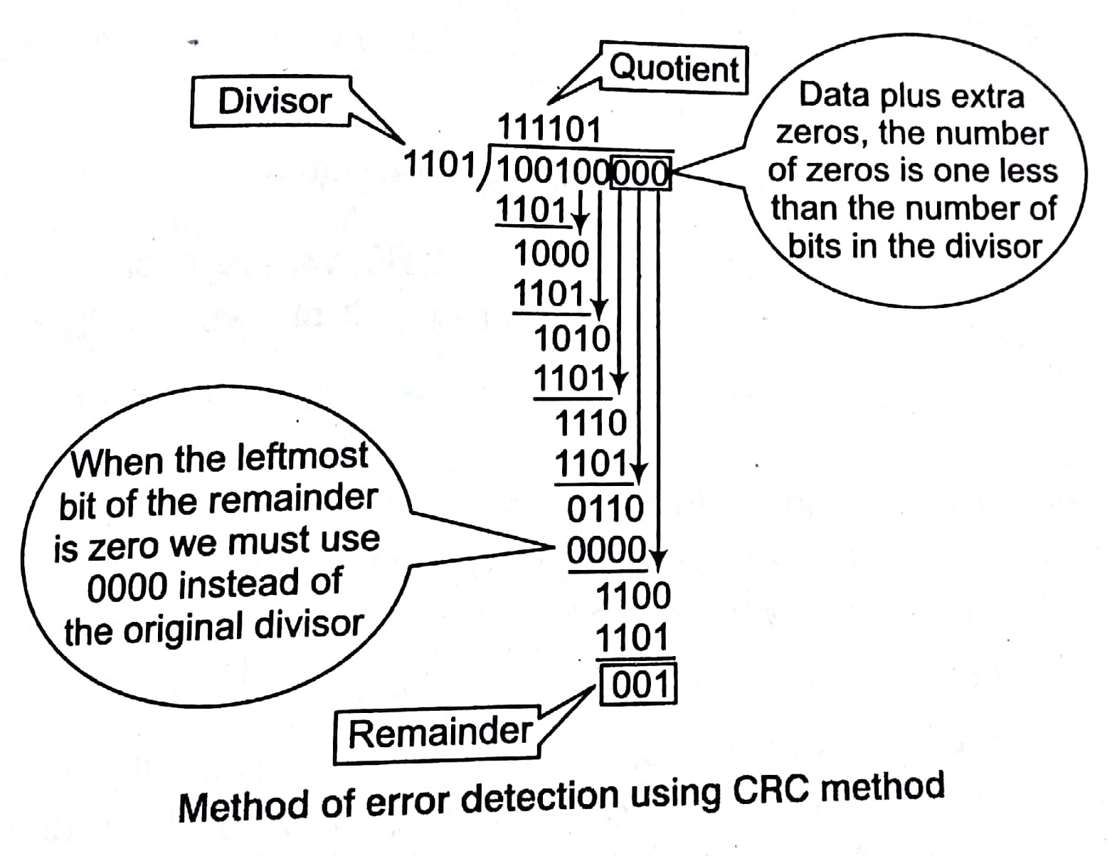
Note: Each bit of the divisor is subtracted from the corresponding bit of the dividend without distributing the next higher bit.
In the above example, the divisor 1101, is subtracted from the first 4 bits of the dividend, 1001, yielding 001 (the leading 0 of the remainder is dropped off).
So‘ here we get input ‘data stream for receiver that is original data plus input stream = 10010001
Now, we perform CRC checker process. Here, we again perform the same modulo-2 division. If the remainder is all zeros, the CRC is dropped and data accepted. Otherwise, the received stream of bits is discarded and data is resent.

We received remainder as all zeros, so the CRC will be dropped off and data (100100) will be accepted at receiver end. It shows that there is not error in data.
Performance of CRC
CRC is very effective error detection method, if the divisor is chosen according to the mentioned rule i.e., A polynomial should be selected to have at/east the following properties to be a divisor.
- It should not be divisible by x • It should be divisible by (x + 1)
The first condition guarantees that all burst errors of a length equal to the degree of the polynomial are detected. The second condition guarantees that all burst errors affecting an odd number of bits are detected.
Error Correction
Error correction in data link layer is implemented simply anytime, an error is detected in an exchange, a negative acknowledgement NAK is returned and the specified frames are re-transmitted. This process is called Automatic Repeat Request (ARQ). Re-transmission of data happens in three cases Damaged frame, Lost frame and Lost acknowledgement.
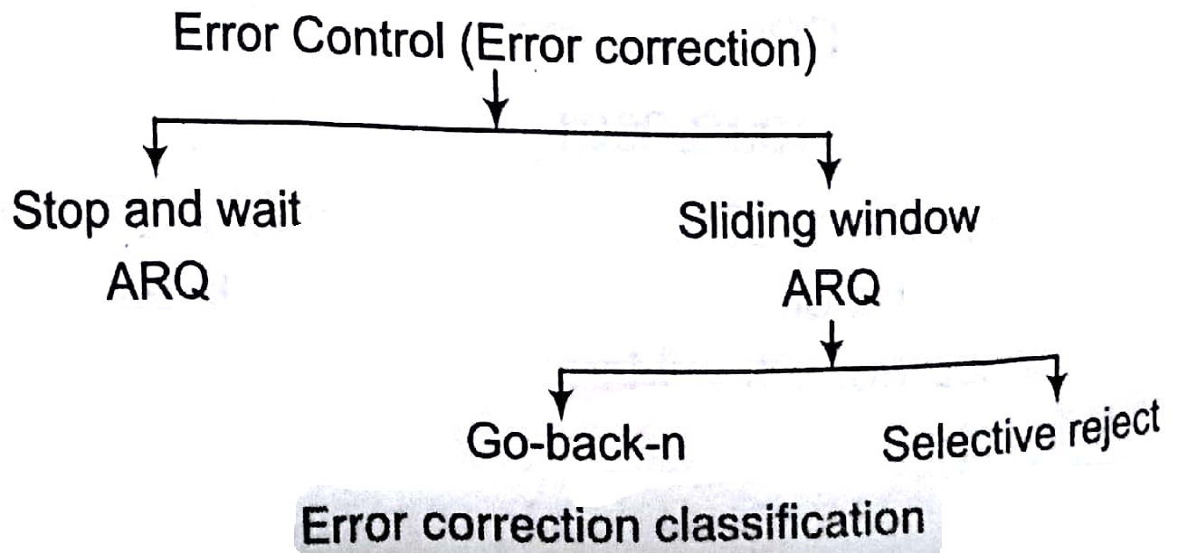
Stop and Wait ARQ
Include re-transmission of data in case of lost or damaged framer. For re-transmission to work, four features are added to the basic flow control Mechanism.
Key Points
- The sending device keeps a copy of the last frame transmitted, until it receives an acknowledgement for that frame.
- For identification purpose both data frames and ACK are numbered alternately 0 and 1.
- A data 0 frame is acknowledged by an ACK 1 frame, indicating that the receiver has gotten data 0 and now expecting data 1.
- If an error is discovered in a data frame, indicating that it has been corrupted in transit, a NAK frame is returned. NAK frames, which are not numbered, tell the sender to re-transmit the last frame sent.
- The sender device is equipped with a timer. If an expected acknowledgement is not received within an allotted time period, the sender assumes that the last data frame was lost in transmit and sends it again.
Sliding Window ARQ
To cover re-transmission of lost or damaged frames, three features are added to the basic flow control mechanism of sliding window.
- The sending device keeps copies of all transmitted frames, until they have been acknowledged.
In addition to ACK frames, the receiver has the option of returning a NAK frame, if the data have been received damaged. NAK frame tells the sender to re-transmit a damaged frame. Here, both ACK and NAK frames must be numbered for identification. ACK frames carry the number of next frame expected. NAK frames on the other hand, carry the number of the damaged frame itself. If the last ACK was numbered 3, an ACK 6 ,acknowledges the receipt of frames 3,4 and 5 as well. If data frames 4 and 5 are received damaged, both NAK 4 and NAK 5 must be returned.
Like stop and wait ARQ, the sending device in sliding wino w ARQ is equipped with a timer to enable it to handle lost acknowledgements.
Key Points
- In sliding window ARQ, (n -1) frames (the size of the window) may be sent before an acknowledgement must be received.
- If (n – 1) frames are awaiting acknowledgement, the sender starts a timer and waits before sending any more.
- If allotted time has run out, sender assumes that frames were not received and re-transmit one or all frames depending on the protocol.
Go-back-n ARQ: In this method, if one frame is lost or damaged all frames sent, since the last frame acknowledged are re-transmitted.
Selective Reject ARQ: In this method, only specific damaged or lost frame is re-transmitted. If a frame is corrupted in transmit, a NAK is returned and the frame is resent out of sequence. The receiving device must be able to sort the frames it has and insert the re-transmitted frame into its proper place in the sequence.
Sorting in Design and Analysis of Algorithm Study Notes with Example
Learn Sorting in Handbook Series: Click here
Follow Us on Social Platforms to get Updated : twiter, facebook, Google Plus