
Routing and Switching Basics for Cyber and Network Security Tutorial
Routing and Network Security
Routing is the process of selecting paths in a network along which to send network traffic. Routing is performed for man y kinds of network, including the telephone network, electronic data networks and transportation networks
Routing can be grouped into two categories.
1. Non-adaptive routing 2. Adaptive routing
.Non-adaptive Routing
Once the pathway to destination has been selected. The router sends all packets for that destination along that one route. In other words, the routing decisions are not made based on the condition or topology of the network.
Adaptive Routing
A router may select a new route for each packet (even packets belonging to the same transmission) in response to changes in condition and topology of the networks.
For this purpose two common methods are used to calculate the shortest path between two routers
- Distance Vector Routing 2. Link State Routing
Routing Algorithms
There are many routing algorithms
- Distance vector Routing 2. Link State Routing
- Flooding 4. Flow based Routing
Distance Vector Routing
In this routing scheme, each router periodically shares its knowledge about the entire network with its neighbors. Each router has a table with information about network (ID, cost and the router to access the particular network). These tables are updated by unchanging information with the immediate neighbors.
Link State Routing
In link state routing, each router shares its knowledge of its neighborhood with all routers in the network.
When a router floods the network with information about its neighborhood it is said to be advertising. The basis of this advertising is a short packed called a Link State Packet (LSP). An LSP usually contains 4 fields: the ID of the advertiser, the ID of the destination network, the cost and the ID of the neighbour router.
Every router receives LSP and puts the information into a link state database. Because every router receives the same LSPs, every router builds the same database. But the shortest path trees and the routing tables are different for each router. Each router finds out its own shortest paths to the other routers by using Dijkstra’s algorithm.
Flooding Algorithm
It is a non-adaptive algorithm or static algorithm. When a router receives a packet, it sends a copy of the packet out on each line (except the one on which it arrived).
To prevent form looping forever, each router decrements a hop count contained in the packet header. As soon as the hop count decrements to zero, the router discards the packet.
Flow Based Routing Algorithm
It is a non-adaptive routing algorithm. It takes into account both the topology and the load in this routing algorithm, we can estimate the flow between all pairs of routers.
Given the line capacity and the flow, we can determine the delay. It needs to use the formula for relay time.

The Optimality Principal
This simple states that if router J is on the optimal path form router I to router k, then the optimal path from J to K also falls along this same Path.
congestion Control
when one part of the subnet (e.g., one or more routers in an area) becomes overloaded, congestion results. Because routers are receiving packet faster they can forward them, one of the two must happen.
The subnet must prevent additional packets form entering the congested region, until those already present can be processed. The congested routers can discard queued packets to make room for the that are arriving.
Factors that Cause Congestion
- Packet arrival rate exceeds the outgoing link capacity
- Insufficient memory to store arriving packets
- Bursty traffic
- Slow processor
Congestion Control Techniques
Several techniques can be employed for congestion control. These include
- Warning bit
- Choke packets These three deal with congestion
- Load shedding detection and recovery
- Random early discard These two deal with
- Traffic shaping congestion avoidance
Warning Bit
A special bit in the packet header is set by the router to warn the source when congestion is detected. The bit is copied and piggy-backed on the ACK and sent to sender.
The sender mentions the number of ACK (acknowledgment) packets, it receives with the warning bit set and adjusts its transmission rate accordingly.
Choke Packets
A Choke packet is control packet generated at congested node and transmission to certain restrict traffic flow.
The source, one receiving the choke packet must reduce its rate by a certain percentage.
Load Shedding
When buffers become full routers simply discard packets. Which packet is chosen to be the victim depends on the application and on the application and on the error strategy used in data link layer.
For a file transfer for e.g., we can’t discard older packets, since this Will cause a gap in the received data. For real time voice or video, it is probably better to throw away old data and keep new packets.
Random Early Discarded (RED)
This is a proactive approach in which the router discards one or more packets before the buffer becomes completely full. Each time a packet arrives, the RED algorithm computes the average queue length, say AVG.
Key Points
- If AVG < some lower threshold, congestion is assumed to be minimal or non-existent and packet is queued.
- If AVG is greater than some upper threshold, congestion is assumed to be serious and the packet is discarded.
- If AVG is between the two thresholds, this might indicate the onset of congestion. The probability of congestions is then calculated.
Traffic Shaping
- Another method to congestion control is to shape the traffic before it enters the network.
- It controls the rate at which packets are sent (not just how many). Used in ATM and integrated services networks.
- At connections setup time, the sender and carrier negotiate a traffic pattern (shape).
Two traffic shaping algorithms are as follows
(i) Leaky Bucket (ii) Token Bucket •
The Leaky Bucket (LB) Algorithm
The Leaky Bucket algorithm used to control rate in the network. It is implemented as single-server queue with constant service time. if is buffer (bucket) overflows, then packets are discarded.The leaky bucket enforces a constant output rate (average rate) regardless of the burstiness of the input. Does nothing when input is idle e when input is idle.

When packets are of the same size (as in ATM cells), the host should insect one packet per clock tick onto the network. But for variable length packets, it is better to allow a fixed number of bytes per tick.
Token Bucket (TB) Algorithm
In contrast to LB, the token bucket algorithm, allows the output rate to vary depending on the size of the burst

Key Point
- In the TB algorithm, the bucket holds tokens.
- To transmit a packet, the host must capture and destroy one token.
- Tokens are generated by a clock at the rate of one token every At se.ce.
- Idle hosts can capture and save up tokens (upto the maximize size of the bucket )in order to send larger bursts later.
Protocols used in Network Layer
Some of the important protocols used in network layer with their functions are given below
Address Resolution Protocol (ARP)
ARP is used to i id the physical address of the node when its Internet address is know .Anytime, a host or a router needs to find the physical address of another has on its network, it formats an ARP query packet that include that IP address and broadcasts it over the network. Every host on the network receives and processes the ARP packet, but the intended recipient recognises its Internet address and sends back its physical address.
Reverse Address Resolution Protocol (RARP)
This protocol allows a host to discover its Internet address when it known only its physical dress. RARP works much like ARP. The host wishing to retrieve its Inter! address broadcasts an RARP query packet that contains its physical address to every host of its physical network. A server on the network recognises the RARP packet and return the hosts Internet address.
Internet Control Massage Protocol (ICMP)
The ICMP is a mechanism used by hosts and routers to send notifications of datagram problems back to the sender. IP is essentially an unreliable and connectionless protocol. ICMP allows IP (Internet Protocol) to inform a sender, if a datagram is undeliverable.
ICMP uses each test/reply to test whether a destination is reachable and responding. It also handles both control and error massages but its sole function is to report problems not correct them.
Internet Grit–up Massage Protocol (IGMP)
The IP can be irvo!ved in two types of communication uni-casting and multitasking. The GMP protocol has been designed to help a multicast router to identify the hosts in a LAN that are members of a multicast group.
Addressing at Network Layer
In addition physical addresses that identity individual individual devices, the internet requires an additional addressing connection an address that identifies the connection of a host of its network. Every host and router on the internet has an IP address which encodes its network number and host number. The combination is unique in principle, no 2 machines on the internet have the same IP address.
classes and Subnetting
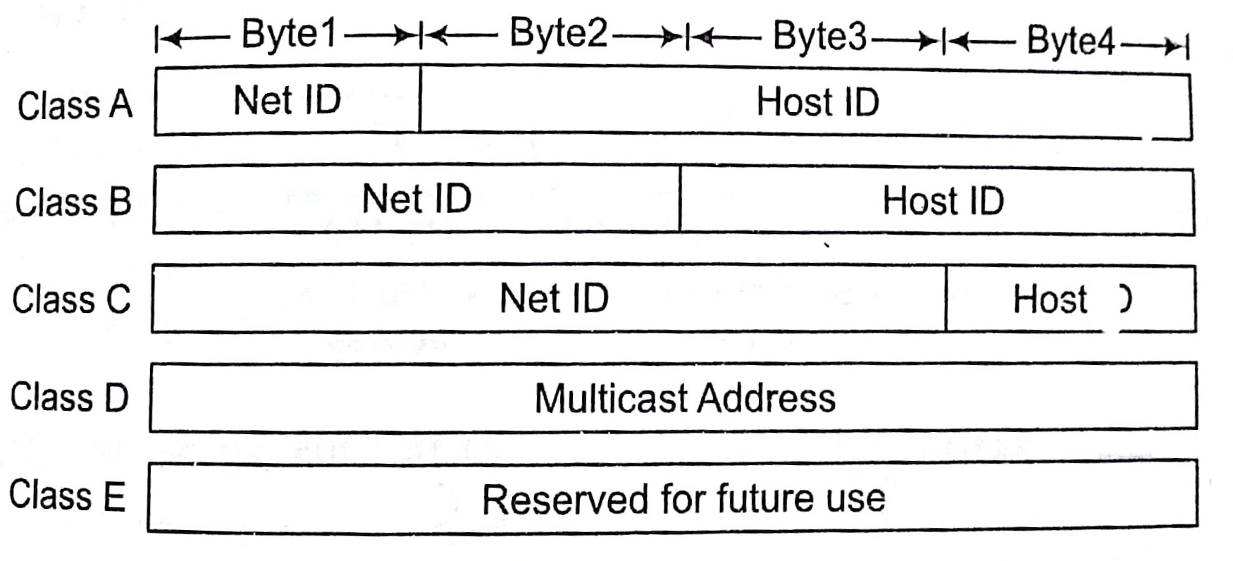
There are currently five different field length pattern in use, each defining a class of address.
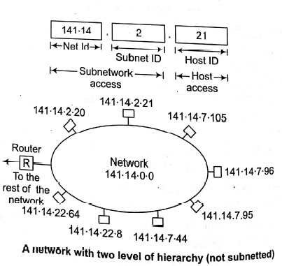
An IP address is 32 bit long. One portion of the address indicates a network (Net ID ) and the other portion indicates the host (or router) on the network ( i.e, Host ID).
To reach a host on the Internet, we must first reach the network, using the first portion of the address (Net ID). Then, we must reach the host itself, using the 2nd portion (Host ID).
The further division a network into smaller networks called sub-networks.
For Class A First bit of Net ID should be 0 like in following pattern
01111011.10001111.11111100.11001111
For Class B First 2 bits of Net ID should be 0 respective, as in below
Pattern 10011101 . 10001111 . 11111100 . 11001111
For Class C First 3 bits Net ID should be 1,1 and 0 respectively, as follows
1011101.10001111.11111100.11001111 and 1110 respectively, as in pattern
For Class D First 4 bits should be 1110 respectively, as in 1011.10001111.11111100.11001111
.Class E First 4 bits should be 1111 respectively, like
1110101.10001111.-11111100.11001111
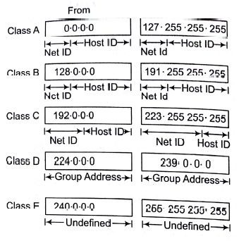
Class Ranges of Internet Address in Dotted Decimal Format
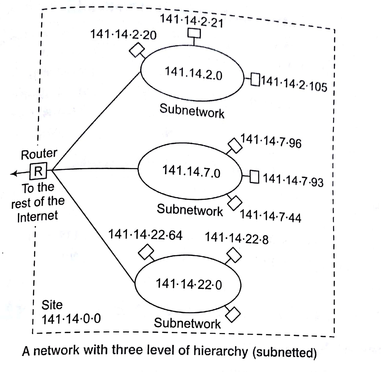
Three Levels of Hierarchy
Adding sub-networks creates an intermediate level of hierarchy in the IP addressing system. Now, we have three levels: net ID; subnet ID and host ID. e.g.,
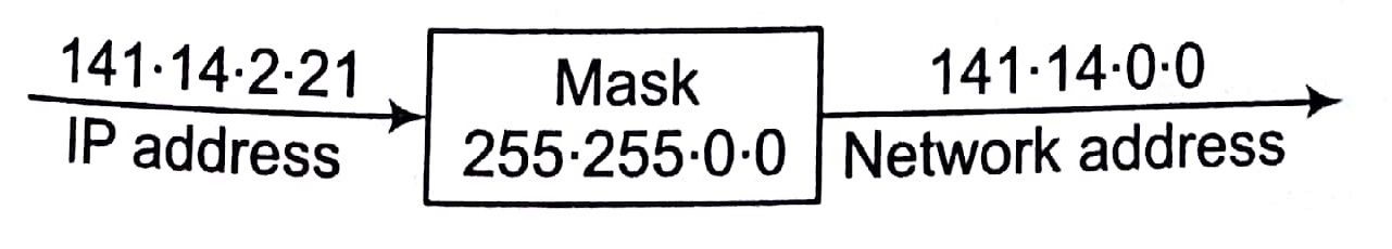
Masking
Masking is process that extracts the address of the physical network form an IP address. Masking can be done whether we have sub-netting or not. If we have not sub-netted the network, masking extracts the network address form an IP address. If we have sub-netted, masking extracts the sub-network address form an IP address.
Masks without Subnetting
To be compatible, routers use mask even, if there is no sub-netting.
Masks With Subnetting
When there is sub-netting, the masks can vary


Types of Masking
There are two types of masking as given below
Boundary Level Masking
If the masking is at the boundary level (the mask numbers are either 255 or 0), finding the subnetwork address is very easy. Follow these 2 rules
- The bytes in IP address that correspond to 255 in the mask will be repeated in the sub-network address.
- The bytes in IP address that correspond to 0 in the mask will change to() in the subnetwork address.

Non-boundary Level Masking
If the masking is not at the boundary level (the mask numbers are not lust 255 or 0), finding subnetwork address involves using the bit-wise AND operator. follow these 3 rules
- The bytes in IP address that correspond to 255 in the mask will be repeated in the subnetwork address.
- The bytes in the IP address that correspond to 0 in the mask will be change to 0 in the subnetwork
- For other bytes, use the bit-wise AND operator.

Transport Layer Protocols
There are two transport layer protocols as given below
UDP (User Datagram Protocol)
UDP is a connection-less protocol. UDP provides a way for application to send encapsulate IP datagram and send them without having to establish a connection.
UDP transmitted segments consisting of an 8 byte header followed by the payload. The two parts serve to identify the end points within the source and destinations machine. When UDP packets arrives, its payload is handed to the process attached to the destination ports.

TCP (Transmission Control Protocol)
TCP provides full transports layer services to applications. TCP is reliable stream transport port-port protocol. The term stream, in this context, means connection-oriented, a connection must be established between both ends of transmission before either may transmit data. By creating this connection, TCP generates a virtual circuit between sender and re that is active for the duration of transmission.

Each machine supporting TCP has a TCP transport entity either a library procedure, a user process or port of kernel. In all cases, it manages TCP streams and interfaces to the IP layer. A TCP entities accepts the user data stream from local processes, breaks them up into pieces not exceeding 64 K bytes and sends each piece as separate IP datagrams.
Key Points
- When a datagram containing TCP data arrive at a machine, they are given to the TCP entity, which reconstruct the original byte stream.
- All TCP connections are full duplex and point-to-point and TCP connection is a byte stream not message steam.
Sorting in Design and Analysis of Algorithm Study Notes with Example
Learn Sorting in Handbook Series: Click here
Follow Us on Social Platforms to get Updated : twiter, facebook, Google Plus