Flip Flops in Computer Architecture Tutorial Study Notes with Examples
Flip-Flops
These are the binary cells capable of storing one bit of information. A flip-flop circuit has two outputs, one for the normal value and one for the complement value of the bit stored in it.
A flip-flop circuit can maintain a binary state indefinitely until directed by an input signal of switch states.
A Basic Flip-Flop
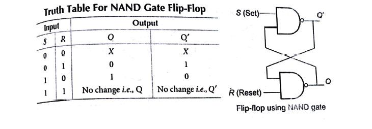
A flip-flop circuit can be constructed from two NAND gates or two NOR gates. SR Flip Flop Truth.

For more understanding let us consider a case when S = 0 and R =1 and the current output of both the gates are Q and Q’ respectively, the 2,7 outputs are working as inputs for the gate 2 and gate 1, respectively. for the first cycle.
R =1 and Q’ will be input for gate 1 so
Q=1+Q=1 and
S = 0 and Q =1 will be input for gate 2 so
Q’ =(0 +1)’= 0
Now these output will again work as inputs for the gates. We will keep on putting these values again and again, until we are not getting the same output each time.
Below diagram illustrates a basic flip flop circuit using NAND gate.

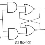
RS Flip – Flop
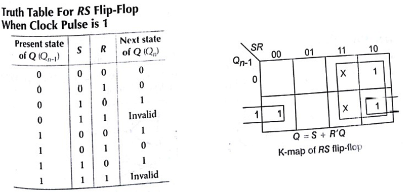
An RS flip-flop is similar to an SR latch. It functions only when clock pulse is 1 or an active clock edge is there. In RS flip-flop S =1 sets the next state value of Q to 1 and R =– 1 resets the next value of Q to 0.

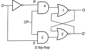
D Flip-Flop
- Modified of RS flip-flop.
- D flip-flop has 2 inputs, data input (D) and clock pulse.
- This will function only when clock pulse is 1 or when the appropriate pulse edge of the clock input is encountered.

JK Flip-Flop
- JK flip-flop is an extended version of the RS flip-flop.
- It has 3 inputs . J, K and Clock Pulse (CP). The J input corresponds to S input and the K input corresponds to the R


T Flip-Flop
- Also known as toggle flip-flop.
- Frequently used in building counters.
- It has 2 inputs, T and Clock Pulse (CP).
- When T 1, the flip-flop changes state after the active edge of the clock. It On_ 1 = 0 (present state of Q). The next state value of Q, will be set to 1. If Qn_1= 1, the next state value of Q will be reset to 0. When T = 0, no state change occurs.

Master-Slave Flip-Flops
- Constructed from two separate–flip-flops.
- One circuit serves as master and the other as a slave.
- Gates 1 through 4 are from master flip-flop and gates 5 through 8 are from
- Master works on the positive edge of clock pulse and slave works on the negative edge of clock pulse.

Sorting in Design and Analysis of Algorithm Study Notes with Example
Follow Us On Cyber Point Solution Youtube Channel : Click Here
Follow Us on Social Platforms to get Updated : twiter, facebook, Google Plus
Learn More Ethical Hacking and Cyber Security click on this link. cyber security
